
This document is to be used as a guide, when assisting RETTEW with Natural Gas projects.
RETTEW Will Provide:
- A sample project
- Templates
- RETTEW-LD-NGAS
- Cleanslate
- Other (Client specific template)
- Shape files
- Plot style (.ctb)
- Contact information
- Survey base plan and topo file
- File structure and design standards
File Folder Structure
The file folder structure should be set up as follows:
The root folder should be the Project#-Name. (Example - 05214683-EastWindsor)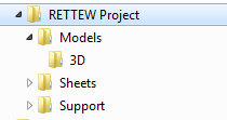
Models Folder Contents:
- RETTEW Project#-LD-BASE.dwg – Proposed line work and labels. (Use “RETTEW LD-NGAS” template)
- RETTEW Project#-LD-GRAD.dwg – Data referenced FG surface. (Use “RETTEW LD-NGAS” template)
- RETTEW Project#-LD-PROF.dwg – Data referenced alignments and profiles. (Use “RETTEW LD-NGAS” template)
- RETTEW Project#-LD-DETL.dwg – Details. (Use “Cleanslate” template)
- RETTEW Project#-SV-BASE.dwg – Existing conditions line work and labels
- RETTEW Project#-SV-ORTO.dwg – Aerial image
- RETTEW Project#-SV-USGS.dwg – USGS topo map
- RETTEW Project#-SV-TOPO.dwg – Data reference EG surface
3D Folder Contents:
- RETTEW Project#-3D-SURF-FG.dwg – Proposed alignments, surfaces and profiles (Use “RETTEW LD-NGAS” template)
- RETTEW Project#-3D-SURF-EG.dwg – Existing surface. (Use “RETTEW SV” template)
Sheets Folder Contents:
- ENS
- RETTEW Project#-ENS Plan.dwg –Xref SV-ORTHO, SV-USGS, SV-BASE, SV-TOPO, LD-BASE, LD-GRAD & LD-PROF. (Use “Cleanslate” template)
- RETTEW Project#-Sketch.dwg – Xref SV-ORTHO, SV-BASE, SV-TOPO, LD-BASE, LD-GRAD & LD-PROF. (Use “Cleanslate” template)
Things to Remember:
- Never data reference and XRef the same drawing. Always keep all Civil 3D objects in a separate drawing.
- Do not modify the SV-BASE or the 3D-SURF-EG at all.
- Keep all drawings clean. If the design changes, delete old alignment & surfaces.
- Only share data that needs to be shared. (i.e. don’t share all surfaces, just the FG)
- To create an Ortho/USGS drawing:
- Place the image file in a working folder on the C drive in the “Images” folder.
- Open a new drawing in Civil 3D and insert the image file into the new drawing.
- If the surface file is too large, Civil 3D will create an additional file (*.mms), AVOID at all cost.
- Verify that all sheet viewports show the proper information required on each sheet.
Grading an Impoundment:
- Begin by roughing in an impoundment with polylines. Determine the size by the given parameters dictated by the governing agency, site and volume requirements.
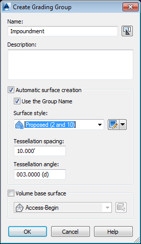
- Create a site and grading group named “Impoundment” in the Prospector Tab under the “Sites” category.
- Create a feature line of the approximate bottom of the impoundment. At this point, leave out the radii at the P.I.’s. It will be easier to manipulate without them.
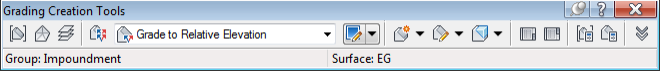
- Open the grading creation tool bar and set the group and target surface. Infill the feature line.
- Grade to relative elevation to the top of the impoundment.
- Grade to distance to the outside of berm. (Usually only on the fill side of the impoundment)
- Grade to surface from the outside of berm on the fill side.
- Grade to surface on the cut side.
- At this point, check the volumes and cut/fill numbers. Take into account that the truck load out area will most likely be all fill. If adjustments are needed, adjust P.I.’s on the bottom of impoundment.
- After satisfied with rough placement, add a sloped bottom (usually -1%) towards truck load out area. Do this with polylines added to the impoundment surface. Also add radii to all P.I.’s on the bottom of impoundment. This will change the volume, be sure to recheck when completed.
- On the cut side, a cut swale is usually required.
- Delete the daylight grading on the cut side.
- Find the midpoint on the cut side.From this point, rough in some points grading 1% down till daylight, in each direction.
- Once the rough locations and elevations are complete, create a feature of the inside bottom of swale.
- Use the “stepped offset” command and offset to outside bottom of swale.
- Add both feature lines to the Impoundment surface.
- Grade to surface from the outside bottom of swale feature line.
- Re-check your cut & fill numbers.
- At this point the impoundment is complete. It is made up of three feature lines (bottom of impoundment and two cut swale feature lines) and one or two polylines for the slopped bottom.
Creating a Pad Surface
- Create a new surface named “Comp-EG-Impoundment”. Paste in the EG and the Impoundment surface. Set the surface to “no display”
- Create a new site and grading group named “Pad.”
- Create a feature line around the pad area. This will usually be on the fill side, just to the outside of top of berm.
- Set elevation to match outside top of berm and grade away a minimum of 1%.
- Open the Grading Creation Tool Bar, set the group, and target the Comp-EG-Impoundment surface.
- Create infill of feature line.
- Grade to surface.
- Create a new surface named “FG.” Paste in the Impoundment and Pad surfaces.
- Run a cut and fill of the EG & FG. If possible, try to balance the impoundment and pad together. If this is not possible, there may need to be spoil stockpiles.
Creating an Access Drive Surface
- Draw centerline alignment with polyline, taking into consideration maximum slopes of access drive, truck turning movement and other site conditions. When satisfied with the alignment layout, note the radius of the curves, then remove them.
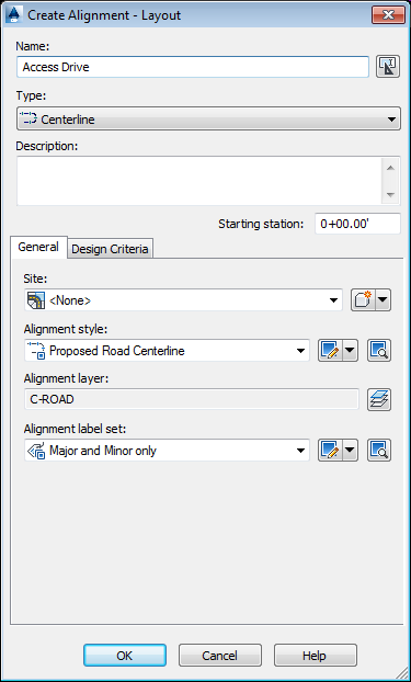
- Open the alignment creation box and name the alignment “Access Drive.”
- Trace the created polyline, starting from the existing road.
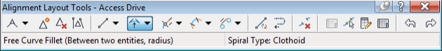
- Add curves to alignment using the “Free Curve Fillet” on the Alignment Layout Tool Bar.
- Create a profile of the Access Drive and EG surface. Follow the Create Profile View wizard. After the EG profile is created, re-name profile “EG-Access” in the prospector tab.
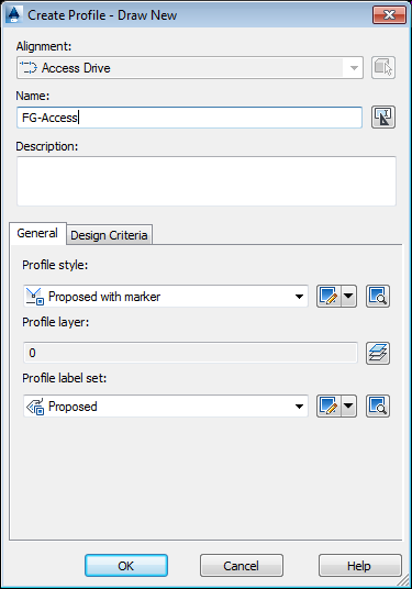
- Create a finished grade profile with the Create Profile Tool Bar. Name it “FG-Access.” With the Profile Layout Tool Bar draw in the rough finished grade profile.
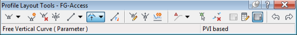
- Add curves to all P.I.’s with the Free Vertical Curve command.
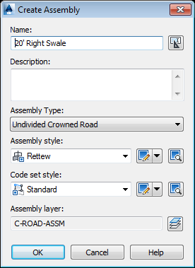
- Create an assembly and name it conventionally.
- Create a new surface named “Comp-EG-PAD” Set it to no display and paste the EG and Pad Surface into it.
- Create a corridor and name it “Access Drive”. Set the Alignment, profile, assembly and target surface.
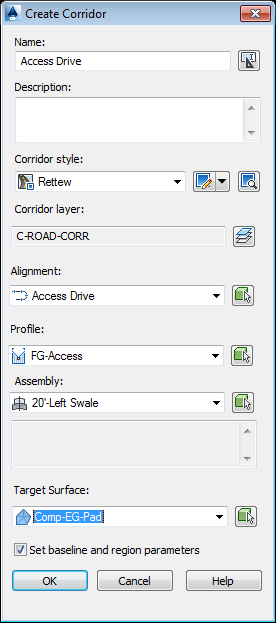
- Set frequencies to 5, and click “OK”.
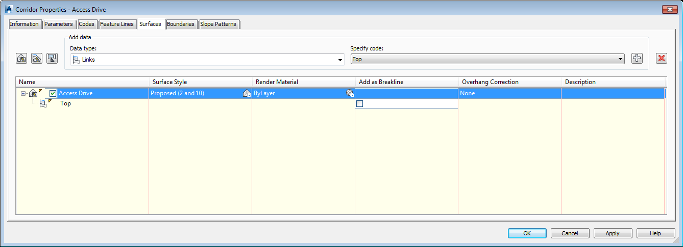
- Open Corridor Properties. Under the Surface Tab, create a corridor surface. Specify code “Top” then click the Add button. Rename Surface to “Access Drive”. Switch to the Boundaries Tab and right click on “Access Drive” and “Add Automatically,” then “Daylight.”
- Depending on the site, more assemblies may need to be added to the corridor. When completed, paste the “Access Drive” surface into the FG and run cut and fill numbers. Adjust accordingly.
Access Drive Flares Surface
- Create a new site named “Access” and grading group named “Flares.”
- This surface will consist of the transition areas that connect the existing road to the access drive and pad.
- At the existing road connection, create a feature line that follows the proposed gravel road where it begins to flare out to the existing road edge. This will be a closed feature line. The elevations of the P.C.’s can be picked up from the Access Drive surface and the existing road edge elevations can be picked up from the EG surface.
- Create a feature line following the centerline of the access drive inside of the closed feature line just created. Use the elevations from surface command to pull elevations from access drive surface.
- Create infills on both sides of centerline.
- For the exterior of the flares, match the template of the access drive. Most of the time that means on the swale side to grade to relative elevation of -2’, then grade to distance of 2’ @ 0% grade, then grade to surface. On the other side, grade to surface targeting the EG surface.
- At the Pad Flares, follow directions listed above, in step 3, with one exception; instead of picking up elevations from the EG, pick up elevations from the pad surface. Also, the Daylight will be targeting the Comp-EG-Pad surface.
- Paste the Flare surface into the FG.
Completing FG
- In some cases, more surfaces are needed:
- Guard Shacks – Put on the “Access” Site and create a new grading group.
- Swales – Put on the “Access” Site and create a new grading group.
- Topsoil – Put on a new site named “Soils” and create a new grading group.
- Spoil - Put on a new site named “Soils” and create new grading group.
- These surfaces will cover most sites. In some cases more surfaces and sites will need to be created. As a rule, keep it simple for others to easily understand the drawing when they open it.
- Make modifications to surfaces in the base surfaces, not the FG. The FG surface definition should only have
pasted surfaces in it, not edits.
Grading a Pad
Pad Surface
- In the Prospector Tab, create a new site and grading group named “Pad.”
- Draw a feature line around the exterior pad. Assign an elevation to it based on best guess to balance.
- If there is a level area, draw a feature line around it and assign elevation based off slope requirements.
- Create infills inside the level area and pad perimeter.
- Grade to relative elevation to the top of berm.
- Grade to distance to outside of top of berm.
- Grade to relative elevation back to the same elevation as the pad.
- Grade to surface targeting the EG surface.
- Check cut and fill volumes and adjust elevations as necessary. Take into consideration that a cut swale will be added.
- Once site is close to being balanced, mark the cut/fill points on the daylight grading object and delete the daylight grading.
- Re-grade the daylight portion on the fill side only.
- On the cut side, a cut swale is usually required.
- Delete the daylight grading on the cut side.
- Find the midpoint on the cut side.
- From the midpoint, rough in some points grading 1% down till daylight each direction.
- Once locations and elevations are set, create a feature of the inside bottom of swale.
- Use the “stepped offset” command and offset to outside bottom of swale.
- Add both of these feature lines to the Impoundment Surface.
- Grade to surface from the outside bottom of swale feature line.
- Re-check cut and fill numbers. Try to balance the pad by itself.
Access Drive Surface
See above - Creating an Access Drive Surface
Access Drive Flares Surface
See above - Creating an Access Drive Flares Surface
Completing FG
See above – Completing FG
Returning Files back to RETTEW
Deliverables shall be as follows:
- CAD files in Civil 3D 2014 format
- Files shall be named and placed in the RETTEW Standard format as described above.
- All files created shall be created using one of the RETTEW template files.
- All files should be PURGED and AUDITED before delivery.
- Files should be zipped and transferred using the RTransfer document management system
- Discuss the frequency of document transfer requirements with your RETTEW contact during the project.
- PDF files of all plan sheets.
Comments
0 comments
Please sign in to leave a comment.